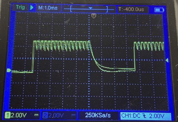
The EEPROM Programmer initially returned corrupted data. I tested wiring, bit ordering, and bus isolation, suspecting noise on the data lines. Oscilloscope traces suggested interference, but the root cause was software, several Arduino address pins were never initialized. These floating pins produced unstable signals that mimicked noise. After proper initialization, the API produced stable results identical to a reference programmer.
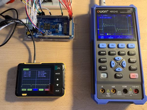
Oscilloscope measurements quantify the execution time of a simple digital pin toggle across multiple Arduino boards. Results show that faster CPUs complete the operation in fewer microseconds, though instruction overhead varies by architecture. The data confirm a near-linear relationship between CPU clock speed and pin toggle performance.
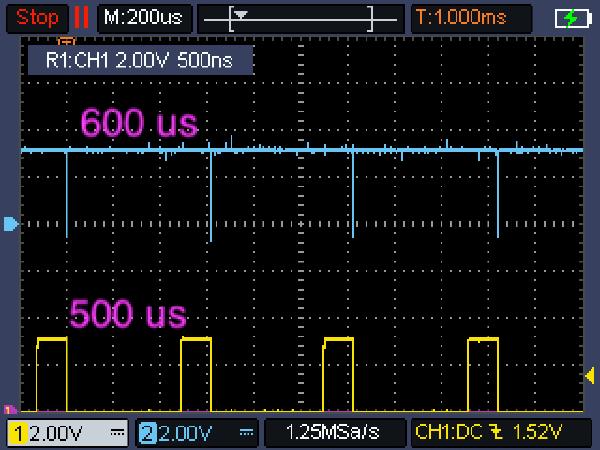
Evaluation of EEPROM Programmer performance on Arduino. Overhead from digital I/O measured, and oscilloscope traces confirmed datasheet timing. Active polling of the READY/BUSY pin reduced write latency while maintaining reliability. Sequential write/read verification showed consistent integrity. Future work includes endurance testing, retention studies, and comparing Arduino boards with different clock speeds.
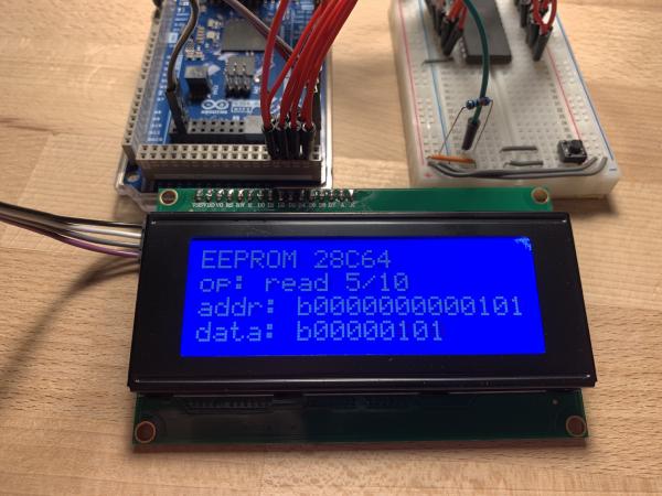
Practical walkthrough of 28C64 EEPROM on Arduino GIGA. Pin mapping, minimal API for reads/writes, breadboard + LCD UI. Verified operation, observed write-edge vs datasheet mismatch, early-address retention issues, and plans for timing and READY/!BUSY testing.
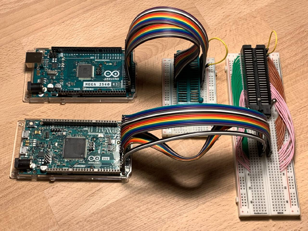
The EEPROM Programmer project uses Arduino MEGA or DUE to read from and write to EEPROM chips from the AT28Cxx family. A Python CLI provides erase, write, read, and verify operations. The series of posts below covers the full development process, from initial implementation to supported chip details.