Several methods for generating ±5 V rails were evaluated, ranging from dual wall warts to regulator-based and buck-boost solutions, with stability, noise, and grounding complexity as the main trade-offs. The most practical approach for the DAC setup proved to be regulator-based supplies, while more complex configurations offered little benefit and higher power consumption.
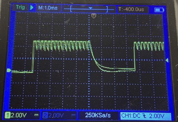
When an Arduino establishes a serial connection, the board resets and produces transient voltage spikes on the EEPROM pins. These fluctuations can reach up to 2 V, enough to toggle the !WE pin and initiate unintended write operations. Tying the !WE pin to VCC during read mode prevents data corruption.
Misconfigured or uninitialized Arduino pins generate unstable voltage levels that vary with frequency and signal state. During board reset, all pins enter a floating state, producing undefined signals that can affect connected devices. This can lead to data corruption or unpredictable behavior in chips such as EEPROMs or DACs.
The EEPROM Programmer initially returned corrupted data. I tested wiring, bit ordering, and bus isolation, suspecting noise on the data lines. Oscilloscope traces suggested interference, but the root cause was software, several Arduino address pins were never initialized. These floating pins produced unstable signals that mimicked noise. After proper initialization, the API produced stable results identical to a reference programmer.
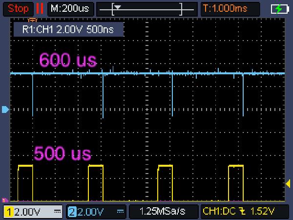
Oscilloscope measurements quantify the execution time of a simple digital pin toggle across multiple Arduino boards. Results show that faster CPUs complete the operation in fewer microseconds, though instruction overhead varies by architecture. The data confirm a near-linear relationship between CPU clock speed and pin toggle performance.
Evaluation of EEPROM Programmer performance on Arduino. Overhead from digital I/O measured, and oscilloscope traces confirmed datasheet timing. Active polling of the READY/BUSY pin reduced write latency while maintaining reliability. Sequential write/read verification showed consistent integrity. Future work includes endurance testing, retention studies, and comparing Arduino boards with different clock speeds.